
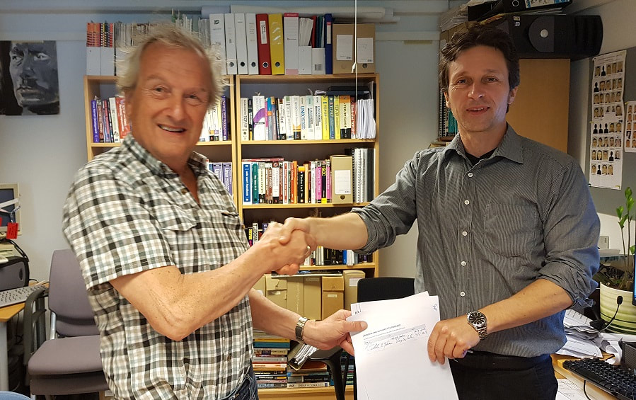
Aiwell and the University of Southeastern Norway sign letter of intent
Cooperation on the development of intelligent water management in smart cities
Recently Aiwell and USN signed an intentional agreement with a 5 years plan which facilitates collaboration at bachelor, master and PhD levels, where the theme is the development of smart cities with new ways to manage storm water, waste water and roof drainage.
Aiwell is currently a partner in the USN System Engineering Industrial Master Program, where the Master's thesis should be directly related to the company's needs. Roar Elias Georgsen is now 2 years into the program (of 3 years), where he plans to continue his 4-year PhD study as part of the intention agreement.
Aiwell is currently a partner in the USN System Engineering Industrial Master Program, where the Master's thesis should be directly related to the company's needs. Roar Elias Georgsen is now 2 years into the program (of 3 years), where he plans to continue his 4-year PhD study as part of the intention agreement.
HSN student oppgave
Aiwell AS has applied for a patent to increase the water capacity of the VA industry using full-flow solutions, or more correctly as a Gravitational Controlled Pressure System, also known as the reversed principle. This has been used for dewatering from roofs for more than 50 years, and is today used over large parts of the world, especially on larger buildings. When using full current in overflow and waste water, the challenge is to let no air into the system. Full power is also used in hydropower plants. There are great forces that occur when the dimensionsof the pipes are increased. This gives the advantage of being able to carry more water through the same pipe dimension as in case of self-fall. Simple tests show that 8.7 times more water can be passed through a 32mm tube at a height difference of 3 meters when using full power. Full vacuum can be achieved at a height difference of 10m.
Aiwell wanted to show in a simple way that the system could also be used to prevent watering and spillage into a common plant. Here this was done using "kummer" consisting of 2 compartments. The one collects overwater and passes it on to a full-flow pipe that is fed into the existing joint pipe. The second chamber captures the waste water coming from the "houses" which are connected to the joint line between the hatches. The spill water flows as the self-fall coupling (branch pipe) and down into the nearest kum and therefrom as full power in a separate line that was also fed into the same joint line.
.
Later in a full version of the plant, we think of the original AF cable (common wire) used only for overwater while a new waste water pipeline is added as a pipe in this pipe. In many cases, it requires the capacity of the AF line. To increase capacity, we will use the Aiwell Water full flow foam method, now built in a full-scale facility in Maria Feghts gt. together with the municipality of Drammen.
As an alternative (if the joint conduit has a small dimension) spill water can be run in its own conduit as a shallow gravel. Running the wastewater into a new pressurized conduit that has been grounded has several advantages, such as: minor digging, can be laid in contraction up to approx. 6-7 m, water speed increases and danger of clogging decreases.
Common wires are often leaky, but now only water will drain and no longer pose a danger to the environment.
We are very pleased that 2 student groups at Buskerud Vestfold University College (HBV) chose Aiwell's Water Project for their main subject tasks. The one group built a scaled-down demo facility that in practice shows how the plant works. Either as a single plant with floats or as an advanced plant with valves controlled by, in this case, a PLS.t very successful project.
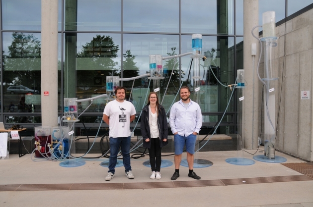
Bilde Gruppe 1
The one groups consisted of Mats Møster Hagnastad (Maritim Elektro Automation) to the left and Madelene Bengtsson and Stian Fossen (Product Design).
A challenge with down-scaled prototype is small pipe dimensions, which provide greater resistance in both pipes and valves. Despite this, they managed to build a very well-functioning facility that worked according to plan. They also showed how the plant could suck the fluid up from a lower lying tank into the system (reversed the principle). Today, this is done by using pumps. Both the facility and the process were duly documented. A very well done task.
A challenge with down-scaled prototype is small pipe dimensions, which provide greater resistance in both pipes and valves. Despite this, they managed to build a very well-functioning facility that worked according to plan. They also showed how the plant could suck the fluid up from a lower lying tank into the system (reversed the principle). Today, this is done by using pumps. Both the facility and the process were duly documented. A very well done task.
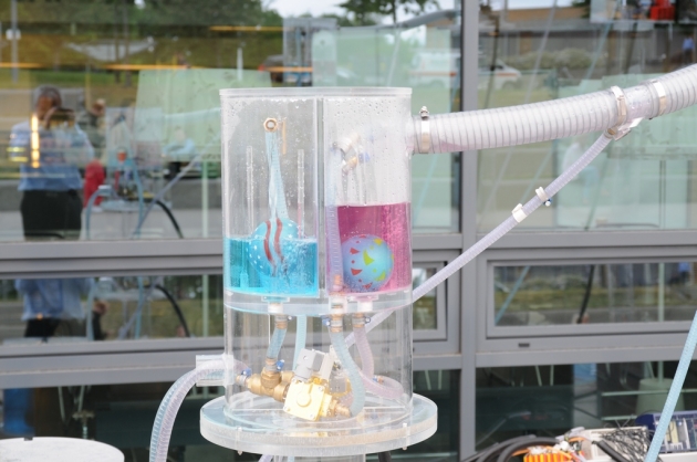
Bilde; kum med flottører
Blue is overwater and red is waste water. This simulates rainwater / overwater (blue) pumped into the cumble, and flows as full flow back to blue tank. The waste water (red) is pumped into the common pipe Ø = 50mm and flows as a self-fall into the first chamber and further as a full flow in hose with Ø = 12mm to the red tank. The balls ensure that air does not escape.
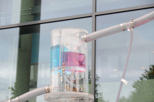
Bilde, Kum med ventiler
The fluid flow in both chambers is controlled by solenoid valves that receive signal from the PLS via level switches. When the upper limit is reached, the valve opens and the amount of liquid is reduced to the lower level and closes before air can enter.
Here it can clearly be seen how waste water (red) is pumped into the common line between this tank and the overhead system. Very impressive that they also got the facility to work with this technique.
Here it can clearly be seen how waste water (red) is pumped into the common line between this tank and the overhead system. Very impressive that they also got the facility to work with this technique.
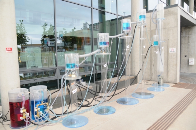
Bilde: Oversikt over kummene
Systemet består av 5 stk. kummer og 2 stk. holding tanker. Kum nr. 1 er den blå som står lengst til høyere i bildet.
På bakken står 2 stk. tanker med henholdsvis spillvann (rødt) og overvann (blått).
Kum-5 med flottører, står 1 meter over bakken. Den tar i mot både overvann og spillvann.
Kum-4 med ventiler, står 1,5 meter over bakken (tredje kum). --------------------«-----------------------
Kum-3 med ventiler, står 2,0 meter over bakken (andre kum). ---------------------«----------------------
Kum-2 med ventiler, står 2,5 meter over bakken. (første kum). Den tar kun imot overvann
Kum-1, står 1,7 meter over bakken og har ingen ventiler. Vannet holdes igjen av ventil i tank-2 (sugerørs effekten). Her viser man hvordan hevert effekten tømmer en lavereliggende kum i systemet, NB: uten bruk av tilførte energi (som pumper trenger) her gjøres det gratis ved å benytte energien i vannet som renner til tankene på bakken.
Tanken lengst bort med klart vann står 3 m over bakken og viser kun hvor effektivt fullstrømssystem er. Her renner det 8,7 ganger mer vann i samme 32mm slange når luften fjernes i røret og tanken tømmes med hjelp av fullstrøm/hevert.
Vi er svært interessert i å komme i kontakt med kunder som har et flaskehalsproblem i sitt overvanns-anlegg, se vår løsning i Maria Feghts gt. i Drammen. Den er rimelig, effektiv og miljøvennlig.
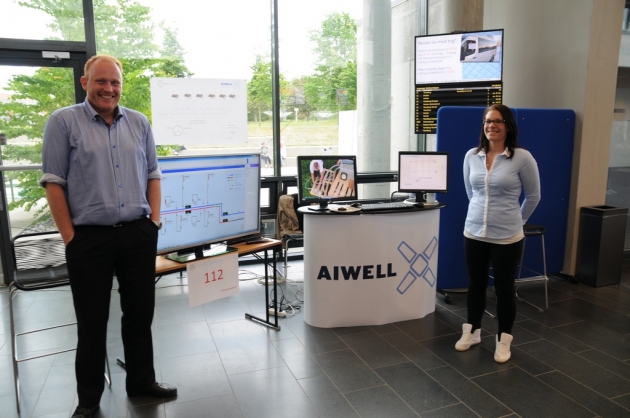
Den andre gruppen. Bilde-2 besto av Ellen Kristine Kristiansen og Espen Buck Edwartsen, begge fra Maritim elektro automasjon.
Denne gruppen viste med simulering hvordan et fullstøms-spillvannsanlegg bestående av septiktanker i hus, boligblokker, eller større felles spillvannstanker kan fordrøyes og på den måten optimalisere tilstrømningen til renseanlegg. Når man har fjernet/redusert overvannet og man tømmer alle septiktankene i løpet av natten kan man ved å regulere mengden i spillvannskummen, fordrøye toppbelastningen og derved øke kapasiteten til et renseanlegg. De viste også hvordan man ved bruk av hevert og beredskapstank i anlegget, bruke fullstrøm/hevertprinsippet til å suge spillvannet over bakketopper med motfall opptil 6-7 meter (teoretisk nærmere 10 meter).
I dette anlegget kunne man også ha lagt inn automatisk selvrensing av spillvannsrørene ved å hente rent vann f.eks. fra en elv, eller fra overvannskummene ved regnvær. Også denne gruppen gjorde en utmerket jobb.
Det finnes svært mange muligheter med fullstrøm, spesielt når man benytter styring og ventiler. I tillegg samsvarer det med Aiwell filosofi, bruke minst mulig energi. Vi styrer kun ventiler, ingen pumper. Det krever kun 12 eller 24 Volt til driften og strømforsyningen kan lett sikres med backup fra batteri, solcelle osv. Stor ventiler benytter 230V